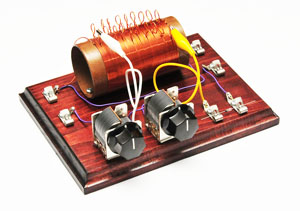
Old-time Radio Fun – No Batteries Required!
Crystal radios are the simplest of radio circuits and have been around since the birth of radio itself. Powered by the radio waves themselves, crystal radios require no batteries, they have very few parts, they’re inexepensive, and they’re relatively easy to build. I stumbled upon a company called the Borden Radio Company that produces crystal radio kits in vintage fashion. I ordered the simple Pickard Crystal Radio kit, and the high performance Dunwoody Crystal Radio kit. Both kits were named in honor of radio pioneers. The Pickard is a crystal radio in its simplest form while the Dunwoody is slightly more complicated, but has the ability to detect signals more precisely and detect some frequencies in the short wave band.


Both kits were packaged individually with the parts nicely protected. They truly have a vintage feel to them, from the clear pine wood base, to the enameled copper wire and cardboard coil tube. The quality seems very good. The pine base has a nice routered edge and the cardboard tube is heavy duty shipping tubing. The knobs for the Dunwoody controls are black bakelite.
The Pickard
I’m going to start with the simpler Pickard radio. I’ve built crystal radios when I was a kid, but they all had the coils pre-wound. Both radios kits from Borden required me to wind my own coils and as you can see with the Dunwoody, it’s a bit more complicated with the reverse loops. The Pickard coil is pretty straightforward requiring me to simply wind the wire around the tube in one direction.

Examining the box contents, you find the pine base, cardboard tube, enameled copper wire, and the smaller parts neatly packaged. The kit also includes an earphone.


The first step is to wind the copper wire around the tube. Start by threading one end through the pre-punched starting holes and crimping the wire
inside the tube to anchor it. Then, using a thumb to guide the wire, use the other hand to rotate the tube to wind the wire around it. Guide the wire so each new loop of wire is right next to the previous loop. You want the individual loops close together, even touching, but do not over lap them. The instructions say to get about 75 loops around the tube after which you’ll come upon another set of pre-punched holes. Again you’ll thread the wire through, leaving about a foot of extra wire free (this will be connected to part of the radio circuit. Now your wire is anchored on both ends.
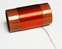
At this time, the instructions recommend spraying the entire coil with clear lacquer. This will seal the cardboard tube from moisture and help keep the coils of wire in place. I got pretty good results by spraying two coats on first to seal the cardboard. I then sanded the cardboard on either side of the coil smooth, taking care not to touch the wire and scuff off any of the enamel. After this I sprayed a few more coats of lacquer. The result was a pretty shiny coil assembly.

After this I stained the pine base a deep cherry stain to get that vintage look. I put a couple of coats of stain on until I got the color I wanted, then I sprayed the base with clear satin finish urethane.

With base finish looking the way I wanted, and the wire coil complete, I am now ready to begin assembling the rest of the components. I started by mounting the coil to the base as per the instructions. The coil is mounted so that the excess wire coming off the coil is positioned near one of the connection points.

Once the coil is mounted, the clips for the antenna ground, earphone are mounted.


The excess wire from the end of the coil is wrapped around some of the screws as per the instructions. Since this wire is enamel coated, the enamel must be scraped or sanded off where it comes in contact with the screws since this is part of the electrical circuit. Then the brass tuning rod is mounted. The tuning rod will be used to tune in the radio stations.
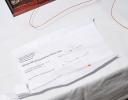
Some electrical components included with the kit must be mounted. These include a capacitor, resistor, and the crystal diode. The instructions clearly indicate where they go. There is no soldering required because the screws and clips hold the components in place.

The tuning rod needs to make an electrical contact with the wires of the coil and since the wire is enamel coated, and I sprayed on a heavy coat of lacquer over the whole coil assembly, the coil must be sanded to get down to the bare copper. This is done by placing a small piece of sandpaper (included in the kit) under the tuning rod and sliding it back and forth along the length of the coil until the coating is removed.
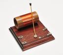
Lastly, the kit provides small felt pads to put on the underside of the base for protection. And Done! The completed Pickard crystal radio.
The Dunwoody

For a greater challenge, the Dunwoody set offers a bit more complexity in construction, but offers greater sensitivity and frequency selectiveness. The Dunwoody uses a more complicated coil assembly, and variable air capacitors to fine tune a wide range of frequencies. Assembly includes more parts and soldering a few connections.

The coil winding is probably the most difficult job in the kit. The smaller loops on the coil are called “taps” and are one of the methods used to fine tune the set. Start by winding the wire around the cardboard tube, just as with the Pickard kit. At every fifth turn, wrap the wire around a pencil and twist to create the smaller loop. There are 20 such taps to make across the 100 turns required to make the coil.


The pine base is given the same stain treatment as the Pickard and the coil is mounted to the base using screws provided in the kit.


Attach the fahnestock fasteners to the board and the two variable air capacitors (the turny knobby thingys). The capacitors are attached with double-sided tape (already mounted to the capacitors). Borden puts marks on the board for the capacitor location. Careful sticking them in place. The adhesive on the double-sided tape is strong and the tape will tear if you try to reposition the capacitor after attaching. Attach the black knobs (real vintage bakelite jobs). Lastly, mount the crystal diode. The diode is fastened to the two clips to the right of the capacitors. At this point, several wired connections have to be soldered into place. The instructions include the wire and a wiring diagram. It was easy to do for a novice like me in less than an hour. Lastly, the felt pads are placed on the underside of the base at each corner.
The Antenna
Crystal radios are extremely sensitive devices, but they require a robust antenna system in order to receive a signal and turn it into something you can hear. Since crystal radios are powered by the radio waves themselves, they require as much of that power as possible. A properly designed and installed antenna system is key to making a workable crystal radio.

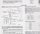
The Borden company offers a pretty nice antenna kit that works well with all of their radio kits. It has all the parts you need to construct an efficient antenna; heavy copper antenna wire, insulators and lead-in wire. What it does not include is an efficient ground (more on that later – it’s fairly easy).
You’ll want to get the antenna as high up as possible and out in the open. I attached one end of mine to the side of the house (a side away from approaching family members and house guests), and the other end to a nearby tree. The antenna is suspended on either end by nylon rope, chosen because nylon is strong won’t conduct nasty lightning into my attic. Plastic insulators at either end of the antenna wire separate the nylon support lines from the actual antenna wire. At the end of the antenna wire closest to the house, one end of the lead-in wire is soldered to the antenna. The other end goes to the antenna clip on the radio.
I’ve read on several crystal radio sites, that as important as the antenna is, the ground is probably more important. All electrical systems must be grounded. The low power of a crystal radio set requires the best ground possible. The best grounding system is a long (eight feet or more) copper rod driven into the ground at least eight feet. Now I live in an area where the soil is very rocky. Past the few inches of topsoil, I can’t get a shovel into the ground once with out striking a rock, so for me, driving a copper rod eight feet into the ground ain’t gonna happen.
Thankfully, the second best ground is a copper cold water pipe somewhere in the house. If your house uses PVC plumbing, you’ll have to do the eight foot copper rod. PVC pipe is non-conducting and won’t work as a ground. Find a cold water pipe that’s close to where you’ll be setting up the radio. For me, it was a cold water pipe in the basement. I ran a wire down the same side of the house as the antenna (again, so no one would see it) into a basement air vent, and to the pipe.

I attached the ground wire (14 gauge insulated copper stranded wire) to the pipe with a pipe grounding clamp. This clamp is made specifically for what I want to do. It’s copper plated, has a center fastener for the ground wire, and clamps on the pipe with two screws. You can get these clamps at a home improvement store, hardware store, or electrical supply house.
With the antenna and ground in place, hook up the antenna’s lead in wire to your radio’s antenna clip and the ground wire to the ground clip.
My antenna works pretty well. I live out in the country about 50 miles outside of Philadelphia. I was able to pick up a number of AM stations in Philly and that same night I picked up a German radio broadcast from…um…Germany, I guess. Yes, if atmospheric conditions are right, you can pick up short wave broadcasts from around the globe on the Dunwoody set. This is because certain radio signals can bounce back and forth between the earth and the ionosphere, allowing them to travel great distances. This happens most commonly at night when atmospheric conditions are ripe. In addition to the bouncing signals, the Dunwoody provides sensitivity to a wider range of frequencies than the Pickard. The Dunwoody provides alligator clips to attach to the coil taps to zero in on a frequency range (including shortwave) and then fine tune the antenna and ground with the variable air capacitors.
Well, this was an enjoyable trip into radio’s past. I plan to do some more of the Borden kits, as well as modifying the Dunwoody and Pickard to use a vintage-style “cats whisker” detector instead of the crystal diode.
[wordbay]crystal radio[/wordbay]
You may also like
Archives
- April 2025
- March 2025
- February 2025
- January 2025
- December 2024
- November 2024
- October 2024
- September 2024
- August 2024
- July 2024
- June 2024
- May 2024
- April 2024
- March 2024
- February 2024
- January 2024
- November 2023
- October 2023
- September 2023
- August 2023
- July 2023
- April 2023
- March 2023
- September 2022
- September 2013
- August 2013
- March 2013
- September 2012
- June 2012
- December 2011
- August 2011
- July 2011
- May 2011
- March 2011
- January 2011
- December 2010
- November 2010
- September 2010
- August 2010
- July 2010
- June 2010
- April 2010
- March 2010
- February 2010
- January 2010
- December 2009
- November 2009
- October 2009
- September 2009
- August 2009
- July 2009
- June 2009
- May 2009
- April 2009
- March 2009
- February 2009
- January 2009
- December 2008
- November 2008
- October 2008
- September 2008
- August 2008
- July 2008
- June 2008
- May 2008
- April 2008
- March 2008
- February 2008
- January 2008
- December 2007
- November 2007
- October 2007
- September 2007

Leave a Reply