Single Tube Nixie Clock

My fascination with these unusual clocks continues and I have a couple of kits in the construction queue. I’m not very experienced with a soldering iron, and even less with electrical components, so this simple one-tube Nixie clock seemed like a good “primer” project to develop some skills.
The Internet is a fantastic resource for we hobbyists. A few choice keywords, and the help of a search engine like Google, and we can find information on just about any topic we need. Take soldering, for instance. There are proper techniques that must be employed while soldering to ensure proper electrical connection, longevity of the soldering joint, and joint strength. Where can you go to learn these techniques? The Internet of course; YouTube to be specific. I found several “how-to” soldering videos, generously provided by experts on the subject. Additionally, I found sites to help me identify electrical component types like resistors and capacitors.
After spending some time amassing this information, I turned to this single-tube Nixie clock kit that I got off of ebay from seller petes_kits to put my new-found knowledge to the test.

The first thing to do with any kit is to inventory the parts. You don’t want to get partway through your project and find that you’re missing a critical piece. I labeled some of the potentially confusing components (like resistors and capacitors). I used the Xacto X-tra Hands unit to hold the round circuit board firmly while I assembled the components. The X-tra hands has a fairly heavy base for stability, a positionable magnifying glass (removed in this photo), and alligator clips to hold the work piece in place. I highly recommend it for this type of work.


Also required is a good multi-meter and soldering iron. The multi-meter pictured above is an Ideal brand that I got from Lowes. The soldering iron above is the Weller WESD51 Digital Soldering Station. This soldering station might be a bit overkill, but, it allows precise temperature control, ultra-rapid heating of the tip, and interchangeable precision tips for the precise soldering work that is sometimes required in the tight confines of a small circuit board.


From this point on it’s a fairly straightforward matter of following the included instructions with the kit. Soldering the components is fairly easy once you’ve mastered the proper technique. I inserted the leads of the components in through the proper holes in the circuit board and bent the leads on the other side to secure the component in place. Then I flipped the board over and applied solder. The various microchips had enough friction to stay put while soldering.


This is the completed circuit board. This particular Nixie clock uses the IN-18 Nixie tube which is one of the larger types as Nixie tubes go. Most smaller Nixie tubes require that they to be soldered to the circuit board, which makes it difficult to replace tubes if they go bad. The IN-18 requires a socket to be utilized. While this can add more work during construction, it means easy replacement of the tube later on. For this particular kit, 14 “mouser pins” are soldered in the collection of small holes arranged in a circle in the center of the circuit board. These pins are essentially small sockets, made to accommodate the individual pins on the bottom of the Nixie tube.

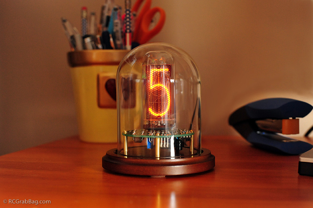
The finished clock sitting on my wife’s desk. So, you may be wondering how a single-tube Nixie clock displays time. It’s pretty simple actually. The clock cycles through the numbers of the current time in sequence from left to right. For instance, if it’s 12:54, the clock will display 1 then 2 then 5 and then 4 in rapid succession.
Now it’s up to me to create some sort of case to display it in. This is where one can get really creative. Perusing the internet, I found other hobbyists that created some truly extraordinary cases for their nixie clocks.

Another quick search on the internet located a small figurine display case with a glass dome and a wood base with just about perfect dimensions for this clock (4.5 x 3 inches). I got these from Potomac Display.
The plan was to mount the clock to the wood base of the display case. Since the circuit board has electrical components on the bottom, I wanted to elevate the circuit board above the base. The circuit board has four mounting holes in it arranged at 90 degree intervals near the perimeter of the board (you can see these holes in the assembly photos above). I got some brass tubing at the hobby shop to make “stilts” to support the circuit board off the base of the display case. I would make four of these stilts, one for each mounting hole. I then glued some plastic tubing inside the brass tubing. The plastic tubing would give the four mounting screws something to grab onto inside of the brass tubing stilts. I then drilled four holes in the wood base of the display case to accept the brass stilts and one more hole to run the power wire through. Voila! The job is done.
Not too shabby if I do say so myself. Kind of looks like some old electronic lab equipment that you can use to ensure that your frankenstein monster is finished on time.
Here is a short video of the clock as the time changes from 6:59 to 7:00:
[wordbay]nixie tube[/wordbay]
Looks like a pretty cool project. I might have to try one of these!
Cool! Where did you get this?
I got these kits from ebay (check links below). This particular kit came from seller petes_kits.
Very cool. I love retro tech. Do the bulbs get hot?
What sort of power is need for running this?
The Nixie tubes do not get hot. Maybe slightly warm but not very much at all, if at all. The power supply is a standard 12v plug-in unit that uses a 2.1mm center socket with a 5mm diameter plug. They are available cheaply just about anywhere.