

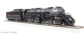
Broadway Limited released the HO scale Y6B 2-8-8-2 locomotive in January, 2010. I received mine in short order and was looking forward to putting it through its paces. But, alas, something was amiss…
Busted gears! The train had way too much play in the drive wheels. When I applied power, the locomotive rolled about an inch and stopped suddenly, motor humming, as if it was bound up. I popped off the boiler and removed the drive gear covers and quickly noticed that some of the drive gears were missing teeth. This was not something that I could fix easily, if at all, so back to the retailer it went. I received a replacement a few days later only to discover it too, had broken gears. In fact, it was worse than the first one. I could find a point in the drive rotation where the drivers spun freely.
Back to Broadway Limited it went. Took about two months, but when I got it back, the chuff sound was gone after a few test runs. It still made noise, but the sounds were the “idling” sounds – essentially the noise the loco makes while hot, but sitting still.
A quick call to BLI and a new electronic “chuff” sensor was in the mail, arriving at my door step a few days later. I could have sent the locomotive back like before, but I didn’t want to wait another eight weeks. And, as a model railroader newbie, it was time for me to learn how to take a loco apart and service it. I was just hoping I didn’t bite off more than I could chew…
The day of surgery:
The new chuff sensor came with a simple printed instruction sheet, but no photos. So, I decided to take a few of my own. Using BLI’s instructions and embellishing a little, here’s how I replaced the sensor…
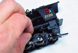
First, detach the detail piping on both sides of the boiler. The detail piping pieces are friction-fit. I used a wooden coffee stirring stick to pry them off and minimize the risk of damage. Detaching from the two mount points closest to the rear of the locomotive is sufficient to provide enough “flex” for the next step.
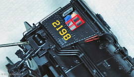
On the rear of the cab are two wire hand rails. With the detail piping out of the way, you’ll see that the wire handrail is bent upwards to lock it into place at the bottom mounting point. Bend this bent section straight so it can be pulled through the mounting hole. This step and the previous step will help facilitate the removal of the boiler which will need to be done in order to get to the chuff sensor.
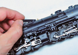
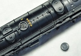
The next step is to remove the sand dome cover to expose one of the fastener screws for the boiler. I used a rounded-tip x-acto knife blade to GENTLY work it into the seam between the cover and the boiler to remove the cover without damaging it.
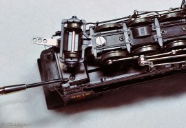
Last step to boiler removal is to remove the two screws under the cab. There is one on the right and left sides.
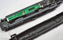
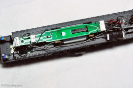
Carefully lift off the boiler and you’ll note the long circuit board. The chuff sensor is located on the underside. It is surface-soldered on the circuit board and will have to be desoldered to remove it. To do this, I found it easiest to 1. Disconnect the large white connector at the end of the circuit board, 2. Remove the tape holding down the wires on top, and 3. Flip the circuit board over and “re-mount” it upside down. Secure it in place with one of the mounting screws. Doing this gave me a nice firm work surface, steadied by the weight of the locomotive. Once this was done, it was an easy matter to heat both ends of the sensor leads to melt the solder and remove the defective sensor.
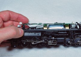
Tilting the loco slightly, it can be seen that the sensor is somewhat raised off the surface of the circuit board, as evidenced by the small amount of visible space beneath the sensor. The new chuff sensor’s soldering points are pre-formed to ensure that it too will sit elevated off the circuit board when mounted.
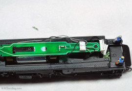
Not much drama in this photo, except that the new sensor is mounted and the old one sits on the work surface above the loco. The sensor is tiny, but easy to handle. To mount the new sensor, tin the ends of the sensor mount leads with solder. Position it in place and apply heat with the soldering iron to the leads to melt the solder and secure the sensor in place. The BLI instructions do not mention any directional orientation for the sensor, so I assume it’s not important, so long as the leads contact the original mounting points. The instructions did say to mount the sensor as far forward as possible while still maintaining contact with the original mounting points. This will ensure that the sensor is close enough to the magnet in the flywheel to trigger the sensor.
A quick hook up of the tender and a short test run and, Voila! The sounds of a hard working locomotive came through loud and clear! Now it was a simple matter of putting everything back in place nice and neat and sitting back and admiring the fruits of my new-found servicing skills.
The moral of the story is that BLI makes great products, but occasionally, like with any manufacturer, a lemon rolls off the assembly line. The BLI Y6B is a remarkably detailed model, it’s loaded with features, and its weight ensures that it can probably pull a couple of scale miles of freight cars. Now that mine is operating normally, it’s smooth as silk. It was an exercise in patience to get to this point, but I’m here at last. I’m hoping this Y6B’s problems are put to rest for good. For now, it runs as good as it looks.
How about 2 Y6B’s double-heading a 100+ car coal drag?:
[wordbay]broadway limited y6b[/wordbay]
Originally posted 2014-11-28 03:40:50.
If you would like to make a comment, please fill out the form below.
Bad Behavior has blocked 430 access attempts in the last 7 days.
I had broken gears too and had a replacement loco shipped. So far the chuff sensor is working on the new one, but if it breaks I’ll know where to find out how to replace it.
Nice article! Wish I had this when I replaced mine. Wasn’t too difficult tho’..
I noticed that you had taken off the worm gear cap and I wondered how you did this. I have the holder model and wanted to change the rear in-synch drivers. my circuit board wires are very short so I can only move it just ever so slight and BLI says pick off the cap. The exploded parts diagram shows the cap is fasten my snapping the cap down but not enough room to lift the cap off.Have attempted this twice without any luck.
Bob
The wires on the circuit board of my Y6B all had plugs, so I was able to unplug the wires and completely remove the circuit board from the loco so I could pop the worm gear cover off. Does the older Y6B have plugs on the ends of the circuit board wires ?
The older y6B does not have plugs on the ends of the circuit board wires. In fact the instructions indicate to be careful when removing the board to prevent pulling the wires loose. I guess I could de solder the wires then solder them back on when I finish the job.
Yep, that would be my suggestion.