


Most ready-to-run locomotives come with exploded view diagrams of the model as part of the included documentation. Exploded views are great for seeing what makes it “tick”, but they are often devoid of many of the “how-tos” needed to assemble/disassemble a delicate item like this loco.


Once again I was late to the party when the FEF’s from Athearn came out (2007?). But my local hobby shop had a DC version sitting in their display case for all this time, even though they were sold out everywhere else. Unfortunately (and I do mean unfortunately), this was the DC version. I run DCC and I wanted sound, so I would need to install a DCC decoder. That’s not normally a big deal as most DC locos offered these days are “DCC-ready”, with a plug-in socket for your favorite decoder.
This FEF-3 was also similarly configured. It was DCC-ready and had ample room in the tender for both the decoder and speakers. The problem was getting inside the tender…along with a few other issues along the way.
I would love to show you photos of the actual breakdown, but I was so engrossed in figuring out how to do it that I couldn’t make time for taking photos. So, I’ll be stepping through the process after the fact.
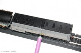
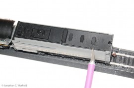
There are two screws that fasten the tender to the chassis. To get the front screw out took me a while to figure out, but basically, you need to pop off this box just about in the middle of the tender (left photo). Once you pop that off, the deck in front of it can be slid towards the rear of the tender and lifted out. This is impossible to tell from the exploded diagram, and there are no instructions for this. As a matter of fact, the instructions were for the sound-equipped version only. The second screw is under the rear-most water fill hatches (right photo). Carefully pry that up and the screw is right underneath.
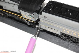
Lastly, remove the grab rails on either side of the front of the tender. They are press fit at either end into the plastic tender body. Once this is done, you can carefully work the tender body off of the chassis. I was so engrossed in trying to figure all of this out, that I didn’t take photos during the disassembly process, so these are after everything was installed. But, once the tender body is off, it’s a simple matter of putting the speakers and decoder where you like. As I said earlier, there is ample room inside.
So up to this point, I’m into the process of disassembly for at least an hour or more. I installed a Soundtraxx Tsunami TSU-1000 Heavy Steam decoder, a 1″ High Bass speaker, and a 1″ regular speaker. All of these items were obtained from Traintek. Athearn locos allow you to use either the standard NMRA 8-pin decoder socket, or the 9-pin JST “Quick Plug”. If you’re using the JST with the TSU-1000, you have to peel off a bit of the heat shrink wrapping around the decoder in order to pull the existing wiring harness out of the JST socket. You’ll also need to pull the dummy plug out of the loco’s harness (the dummy plug is used for DC operation only). Once you do these two steps, you can plug the harness from the loco into the decoder socket. Couldn’t be simpler.
I should have been done at this point, but this is where the real problems began. With the decoder installed, I fired up my NCE PowerCab controller for a test run. The loco wouldn’t move. In fact, the loco was acting like it was shorting out. It ran just fine in DC prior to the decoder installation, but just won’t go in DCC. I even hooked the DC power supply to the test track (the decoder allows the train to run on DC as well as DCC), but the loco wouldn’t move.
I thought it might be the Athearn PCB (printed circuit board) inside the tender shorting out. I pulled all the wires off of it to get a direct line to the loco. Still acted like it was shorting out. With the tender’s PCB out of the equation, the culprit had to be the loco. Ugh, after my battle with the tender disassembly, I was not looking forward to the loco disassembly.
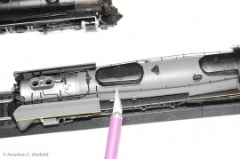
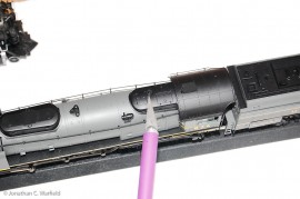
Two screws hold the boiler down. One is under the sand dome (left photo), the other is under this small cylindrical doo-dad (right photo). Getting that little piece out without damaging it was an exercise in temper control. This whole project was. If I was one of those wealthy do-it-yourselfers who could afford anything, this loco would be embedded in the workshop wall or splattered in a jillion pieces on the floor. I’m getting upset writing this! OK, easy. Once the two screws on the boiler are removed, pop out the ends of the two grab rails on the front of the boiler, and the two on the rear of the cab. Four in all. You can simply pop one end off each. Now, gently remove the boiler.
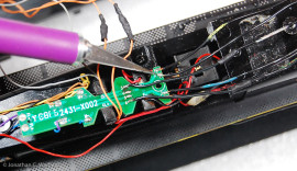
Here’s what I found in the loco that was making ME loco. The loco also has a PCB, just like the tender, only smaller. Wires coming in from the tender and track attach to this smaller PCB and direct power to the appropriate place like the decoder, motor and lights. Two of the wires were reversed (the X-Acto blade is point to the two). One wire is a track pickup lead (all black wire), the other is a lead to the motor (black wire with splotch of yellow). This meant that a track pickup wire was directly feeding one pole of the motor with current.
Now the problem of shorting out while operating in DCC made sense. In DC, DC current is fed to the track by a DC power supply. Having this DC current fed to the motor directly from the track through the swapped wire was not a problem. The motor runs on DC current, and throttle is controlled by the DC power supply by varying voltage to the track. So running on DC was perfectly normal.
In DCC, AC power is fed to the track. The motor requires DC current. The decoder converts the AC current to DC current for the motor. With one of the track pickup leads connected directly to the motor, one of the motor’s poles was receiving AC power. Not good. Once I swapped these wires and ran on DCC, it worked perfectly.
In the photo above, the wires with the yellow and blue splotches are the motor leads. These should always get DC current – either provided by the decoder, or the PCB in the tender (when a decoder is not installed). The yellow and blue splotched wires should be both on the inside solder pads. As you can see in the photo, the blue wire is on the inside pad, but the yellow is on the outside. These color coded wires can be traced all the way back into the tender, so you’ll see yellow and blue wires coming off the PCB’s in the tender. They all make up the electrical path to the two motor leads.
Anyway, there you have it. I’m getting better at these DCC conversions, and I have many more in the fleet to do. One at a time. For now, that’s one more loco in my expanding DCC fleet.
Here’s a video of the FEF-3 pulling a string of Walthers passenger cars. [wordbay]athearn genesis ho[/wordbay]
Originally posted 2015-01-24 06:33:17.
If you would like to make a comment, please fill out the form below.
Bad Behavior has blocked 626 access attempts in the last 7 days.
Do Athearn still make these locos?
They were produced in 2007-2008 and have been sold out for a while. They show up on ebay from time to time (check for links above).
I appreciate all the information you gathered and shared here. It was extremely valuable to me.
I have one of these models, Road #838 that is factory DC. I thought that by plugging a decoder into the 9-pin JST connector, and removing the 8-pin NMRA jumper board, that all would be right with the world. Sadly this is not the case. I too experienced the locomotive working for a stretch and then just stopping, then working again, etc. Having found this write up of yours, I realized I must have a couple of wires to swap inside the boiler. Sadly, after taking both the tender and boiler apart, the wires appeared to be landed correctly according to what you found. I thoroughly checked all the wiring from front to back, loco to tender, with my meter and found that it is in fact wired for correct operation. The motor lead and rail lead that you experienced to be crossed, on my unit they were not.
So now I’m not sure why the loco performs the way it does, but I’m 99.9% certain it is not faulty factory wiring. I come to that confidence because of your hard work in documenting your fix. Thank you again!